As of this blog post, I have now confirmed my project title with my supervisor with my statement of intent. I started off with the more general title of “How can I develop my technical art skills” to “How can I develop my technical art skills to efficiently optimise the game development pipeline?”. This is a more specific question that will help me hone my research and makes it more relevant to the course.
Throughout the past few weeks, I have collated multiple sources in different forms for research for the module. I created a YouTube playlist of videos and tutorials, a bookmark folder for articles/websites related to technical art and borrowed books from the library related to the general subject area. These have fueled my enthusiasm to get started with experimenting and exploring technical art through my own art.

One of the videos I saved was a video entitled “An introduction to Shader Art Coding” by user kishimisu on YouTube (kishimisu, 2023) . I felt like this would be a solid place to start as it’s only 20 minutes long and appears to be user friendly.
The tutorial utilises a platform called “Shadertoy” (Shadertoy, 2023) , which uses GLSL (OpenGL shader language) to procedurally render user-inputted code. The platform is used to develop different shaders and experiment with graphics programming.
This tutorial focused on covering the basics of shader art and graphics programming, which suited my needs well. It taught me the ways of thinking I needed to get myself into to start creating my own shaders and referenced a bunch of useful resources to help me along my way.
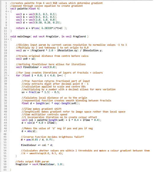
The code I created outputs a 2D fractal shader, using functions such as cosine, sine, power and exponent. The comments I made within the code are notes explaining what each line/section of code does so that I can easily reference back to it.
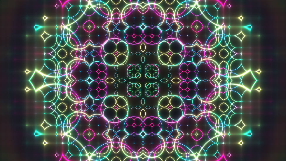
Here is what the final shader looks like as a reference before I get into all the technical code (amelielundrigan, 2023).


The first function vec3 palette() creates a colour palette from 4 RGB vectors. These vectors are then parsed through a cosine function to produce a gradient between the colours.

Void mainImage() takes an input parameter (fragCoord) which holds the X and Y values of each pixel and outputs fragColor which contains the RGBA values of each pixel.

In GLSL, the fragCoord value should be normalised as a value from -1 to 1 so adhere to co-ordinates in clipspace. This is why the vec2 ‘uv’ is created – it calculates a normalised value so the graphics presented are centered on the canvas and so the output isn’t fixed to the canvas resolution. iResolution holds the values of the canvas size in pixels (x,y,x) – the .xy and .y prefixes are used to obtain the x,y and x values of the canvas resolution respectively.
‘uv0’ is created to keep track of the original ‘uv’ value as it is manipulated further in the code.
‘finalColour’ is defined and set to (0, 0, 0) (black) at this point in the code so it can be manipulated to create iterations later in the code.

Then a ‘for’ loop is created. This allows for multiple iterations of the outputted graphics to be layered ontop of each other, each with slightly altered outputs based on the iteration number. The loop I created loops 4 times.

The uv value is then manipulated with a ‘fract’ function. This returns a fractional part of the input using the digit after the decimal point. The value is then scaled and centred. Scaling the uv value by a number with a decimal place value allows for more variation with layers.

The float value ‘d’ is defined which will eventually be multiplied by an adapted RGB value to produce the final visual. ‘length(uv)’ calculates the distance of value ‘uv’ from it’s local origin. This is multiplied by an exponential function which results in smooth blending between fractal segments.

A vec3 variable ‘col’ is defined which will hold an RGB value. The ‘palette’ function I defined at the start is called here, with the return value being assigned to ‘col’. This function takes the input of a singular float, which is used to calculate the palette. The input value is calculated as such:
Length(uv0) - The distance from the origin of the canvas is calculated
I * 0.4 – The iteration number is included in the calculation to create variation between layers. Multiplying by 0.4 increases the contrast and makes the background appear darker.
iTime * 0.4 – iTime holds the number of seconds since the animation has started, therefore manipulating the palette colour for each pass based on how long the animation has been running. This allows for variation between layers.
The ‘d’ float is then further manipulated. A sine function is parsed with a calculation as it’s input. This outputs an infinite loop of rings which are animated due to the ‘iTime’ value, which controls the speed of the animation.

The float ‘d’ is then passed through the ‘absolute’ function – what I’ve written in the comment here isn’t necessarily correct. The function calculates the distance of the inputted value from 0. Say if my value was -4, the function would return 4. If I inputted 8, the value would return 8. This controls the blur/haze of colour around each ring.

‘d’ is then parsed through the ‘power’ function. The inverse calculation 0.01 / d controls brightness falloff. When inputted through a power function, this controls the contrast and makes the darker values appear closer to black.

Almost finished – the ‘finalColour’ value is then assigned as the ‘col’ value (RGB palette value) multiplied by ‘d’. An addition assignment is used here so after each iteration, the calculation is performed and added to the pre-existing ‘finalColour’ value. The for loop is then closed off.

Outside of the for loop, ‘fragColor’, the output parameter is then defined as a vec4 value holding the vec3 ‘finalColour’ and then a 1.0 alpha value which defines the opacity as opaque. That concludes the code which creates this shader. Here is all the code in full for reference:

This exercise helped me wrap my head around how shaders and GLSL works. I think I made the right decision to start with a 2D style shader as it has helped me understand the basics, and at perhaps a lower level in comparison to some in-engine shaders which are often created using nodes rather than code.
amelielundrigan (2023) Shadertoy beta. Available at: https://www.shadertoy.com/view/dldyzM (Accessed: 3 November 2023).
kishimisu (2023) An introduction to shader art coding, YouTube. Available at: https://www.youtube.com/watch?v=f4s1h2YETNY&list=PL42gZMHWYcvjs5SfnoV4X6ocuSnFQsLwS&index=2&t=1s (Accessed: 3 November 2023).
Shadertoy (2023) Shadertoy beta, Shadertoy BETA. Available at: https://www.shadertoy.com/ (Accessed: 3 November 2023).


Comments